Drachenberry Pi

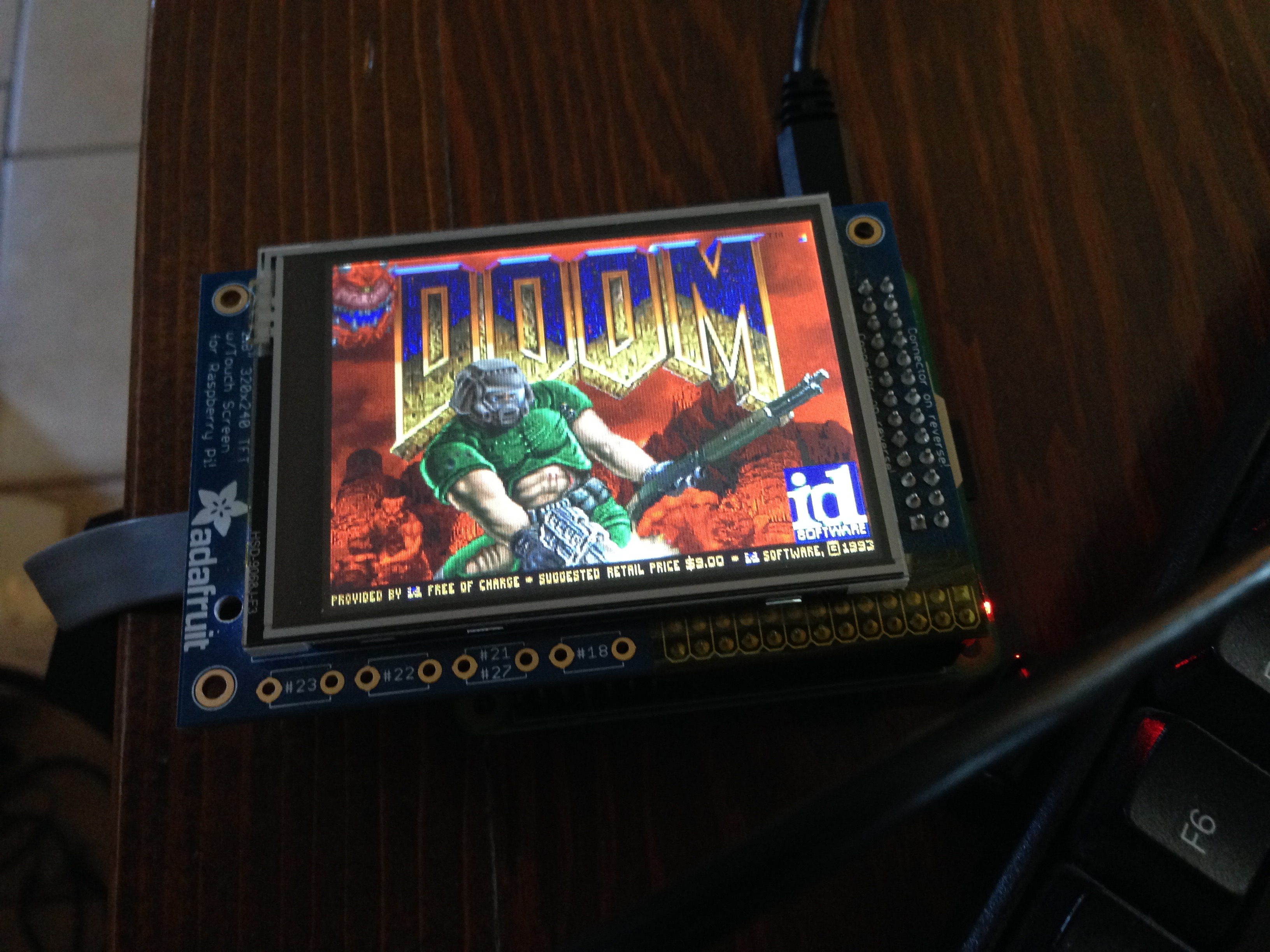
As mentioned at the end of my last post, Adafruit did indeed figure out how to get RetroPie to work using their TFT screens, which was awesome, because it allowed me to use the one I had previously purchased without issue, and finally build my own GameBoy:
Parts List:
2.8″ TFT Touch Screen – Adafruit 1601
PowerBoost 500 Charger – Adafruit 1944 (Haven’t tried it, but item 2465 might be better for this. Also, hold onto that female USB connector. We’ll use that too.)
3.7V 2500 mAh LiPO Battery – Adafruit 328 (Had a few issues with this for some reason and eventually switched to item 353, which changed up the aesthetics of the project a bit.)
Perma-Proto Half-Sized Breadboard – Adafruit 571 (If you purchase everything on the list at the same time, you might get one of these thrown in for free… at least I did.)
12mm Tactile Switch Buttons – Adafruit 1119 (You’ll use four of them for this project.)
6mm Tactile Switch Buttons – Adafruit 367 (You’ll use four of these also.)
6mm Slim Tactile Switch Buttons – Adafruit 1489 (Used two on the TFT.)
SPDT Slide Switch – Adafruit 805
Female-Female Jumper Wires – Adafruit 266
USB Type A Connector – Adafruit 1387
Heat Shrink Tubing – Adafruit 1649
Wifi dongle for Raspberry Pi. I used Adafruit 1012, but there are others
6-32 x 1″ Flat Head Philips Screws – McMaster 91771A153 (You’ll use two of these, so unless you’re going to use them for other things, you can probably grab similar parts at Home Depot, Lowes, etc.)
6-32 x 1 1/4″ Flat Head Philips Screws – McMaster 91771A155 (Four for this project. Can also be found elsewhere.)
If you’re going for the larger battery from Adafruit, you’ll need two 6-32 x 3/8″ Flat Head Philips Screws – McMaster 91771A146 (I couldn’t find an equivalent at Home Depot… Used 1/2″ instead. Bleh.)
6-32 Hex Nuts – McMaster 91841A007 (if purchasing screws elsewhere, the nuts may come included in the packaging.)
2-56 x 1/4″ Pan Head Philips Screw – McMaster 91772A077
2-56 Press-Fit Insert for Plastics – McMaster 92395A111
No. 2 Lockwasher – McMaster 92146A520
Micro SD card
Helpful Tools:
Soldering Iron
3D Printer (or printing service.)
Dremel (Rotary or MultiMax)
Alright… Let’s get down to business…
Set up the Raspberry Pi
Adafruit published THIS guide a while ago covering how to configure your setup to run RetroPie with the TFT screens. At the time of posting, it seems that the guide needs to be updated, but when I started this project, it worked flawlessly.
The guide doesn’t really cover setting up over Wifi, so if (like me) you don’t have a model B, or B+ lying around, you can find more information on that HERE.
If all goes well, you should be able to fire up RetroPie.
Configure Button Inputs
While we’re already digging around in the shell, go ahead and download Adafruit’s Retrogame software. My setup for mapping the buttons to their respective GPIO pins is below.

Feel free to change it up as you please.
Prep Perma-Proto boards
This is where the Dremel comes in handy. Hack up the boards to the sizes/shapes below, and open up holes with a 2.5mm OD drill bit.

Solder-up The Switches
…and solder the wires to the back of the boards using the images below as a guideline.


Solder the slim-tactile switches to the TFT in these two locations.

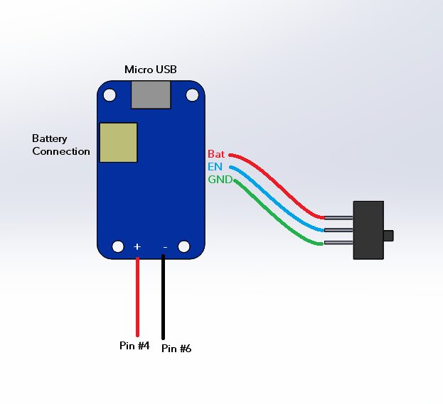
Build the Power Circuit
Connect the PowerBoost to the Pi and the SPDT switch as in the diagram below.
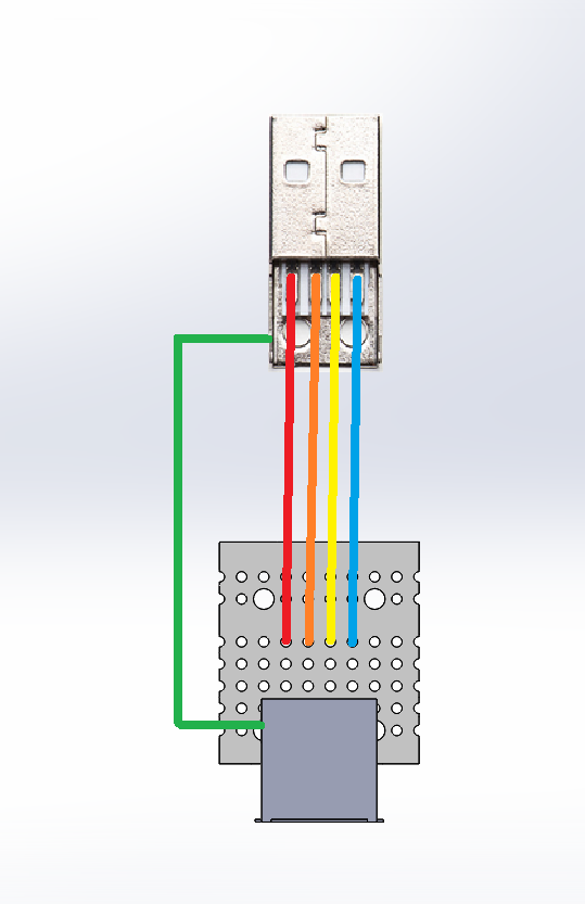
Build USB Extension
Solder the female USB connector that was included with the PowerBoost to the gift that keeps on giving (talkin’bout you, Perma-Proto board), and wire that to the male connector.
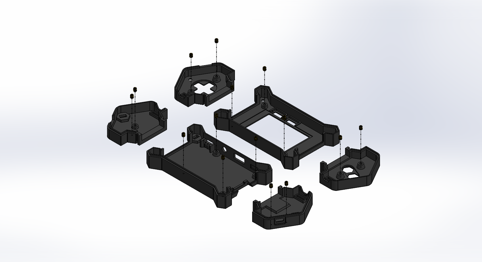
3D-Print Housing and Buttons
Files can be found on my
Thingiverse page HERE. The housing components are designed to print without support and the default PLA settings in Cura. For most of the buttons, I used NinjaFlex SemiFlex material (which you can now purchase in ‘sample’ quantities from Printrbot).11/13/2015 UPDATE: Files can also be found on
YouMagine and Cults3D. If you’ve enjoyed this project, and feel so inclined, consider sending me some love via a donation on Cults3D. No pressure though.5/18/2016 UPDATE: Very proud to also have this work on MyMiniFactory! Still free to download. Tip me if you dare.
4/11/2018 UPDATE: Consolidating the number of places hosting the files. More changes to come, but they’re still available for free.
March 2020 UPDATE: Files can be downloaded directly from this site at the bottom of the page. They are also available on Prusa Printers!
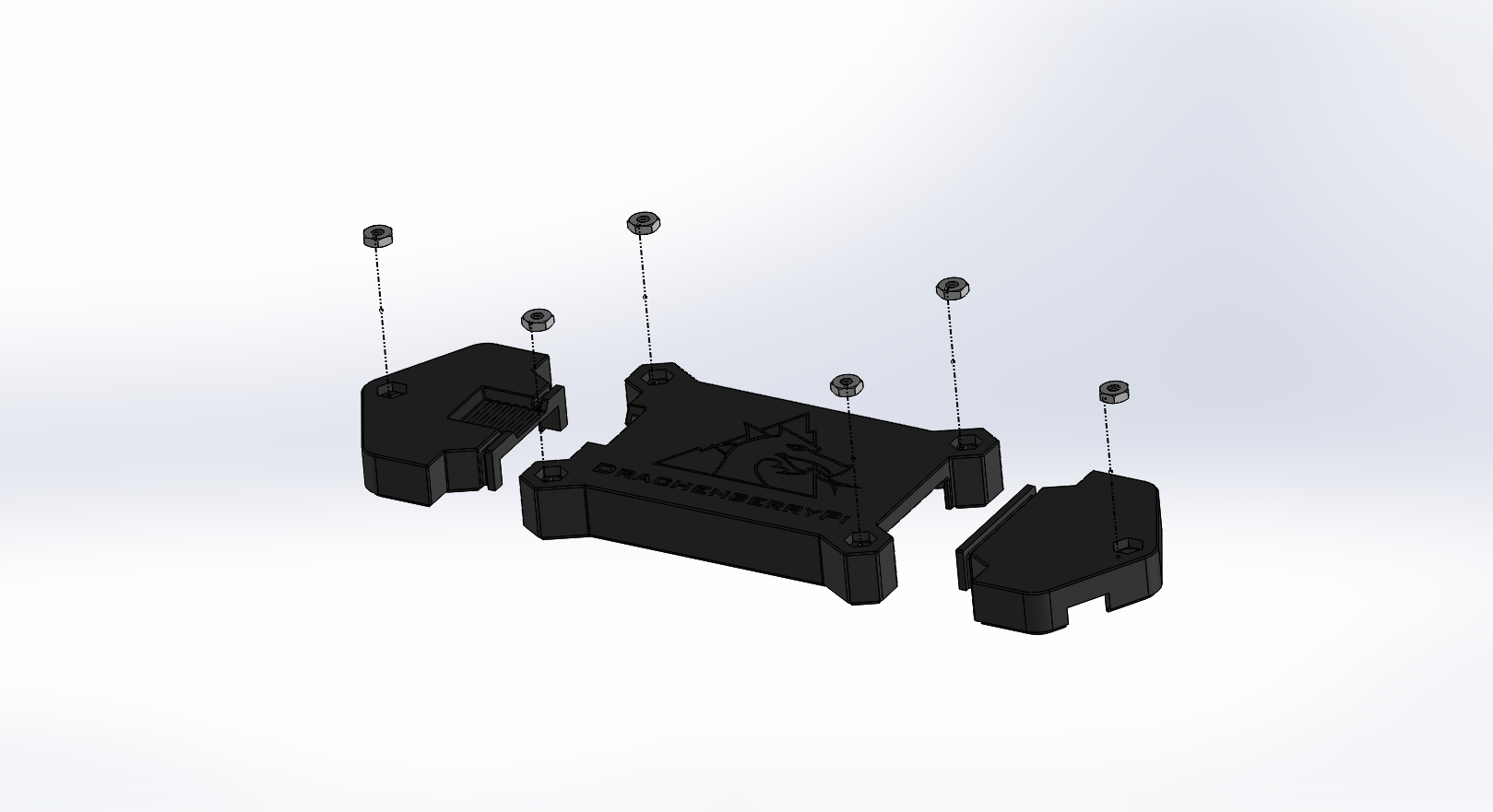
Prep Housing for Hardware
Hex nuts should snugly fit into all their designed crevices.
Install press-fit inserts into the holes as shown (holes may need to be opened up slightly depending on how the print turned out).
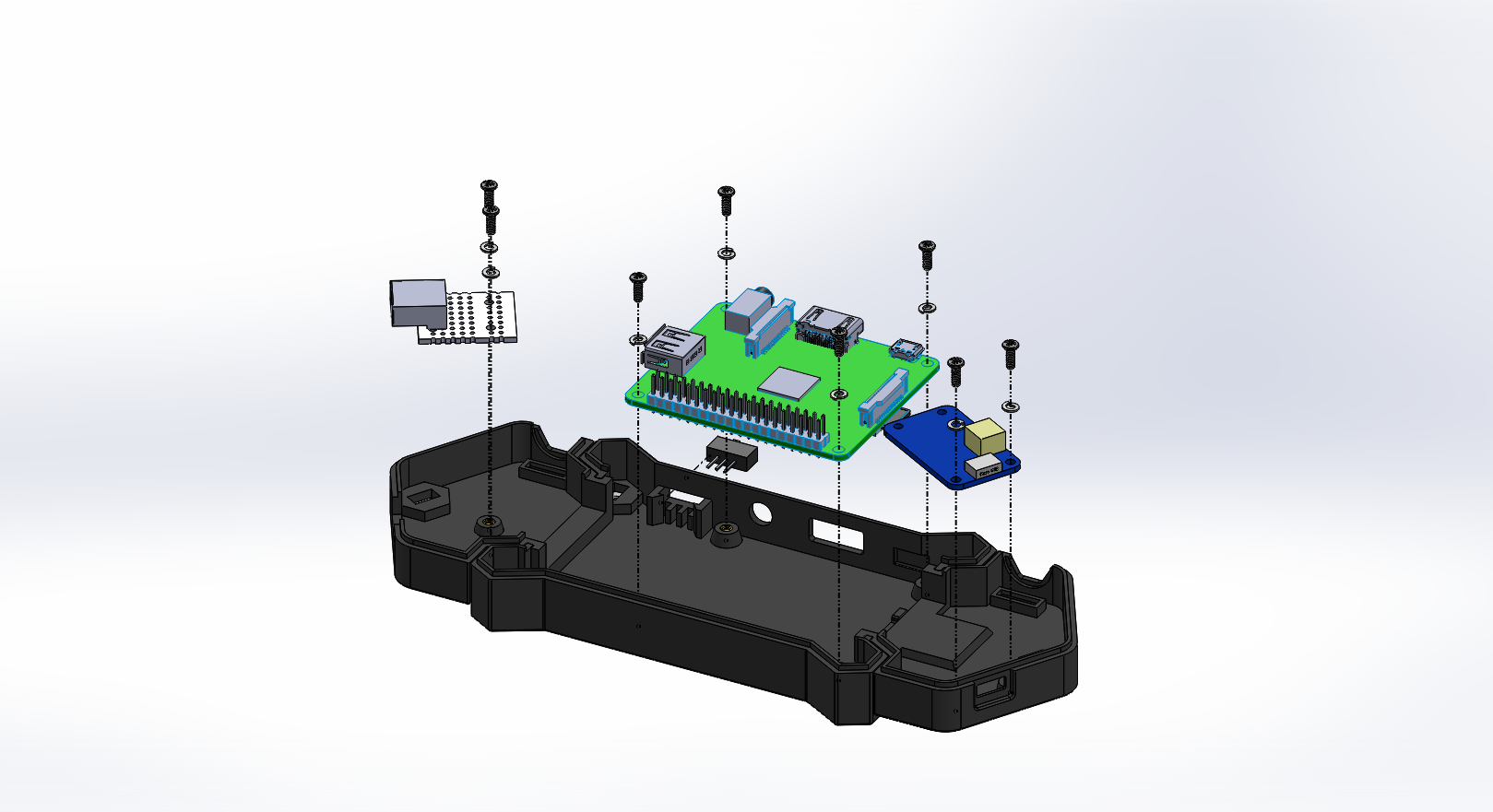
Final Assembly
**REMOVE THE SD CARD FROM THE PI BEFORE ASSEMBLY**
Fit the bottom components together, insert the SPDT switch, and screw the Pi, PowerBoost, and USB extension onto them.
Fit the top components together, place the D-Pad, Start, Select, A, B, R & L buttons into their respective locations, and screw down the Perma-Proto and TFT boards.

Connect all of your wires to the GPIO pins on the Pi. You’re going to want to remove the plastic housings from the connectors on the wires and instead cover them with heat shrink tubing. Otherwise they won’t fit when everything comes together.

Cover the battery with a layer of electric tape, connect it to the PowerBoost, and carefully sandwich it between the Pi and TFT as you line up the pins and close the housing together.

Insert your SD card, flip the SPDT switch to make sure everything works as intended, and secure the housing together with the 6-32 screws.
If You Use the 353 Battery
The hex nuts slide into their spots from inside the battery housing extension.

Place the faceplate within the extension, mount the battery within, and screw the extension to the main component of the main housing base (DBP-3001-01 instead of DBP-3001-00). Make sure the wires and connector of the battery are accessible and can reach the PowerBoost.
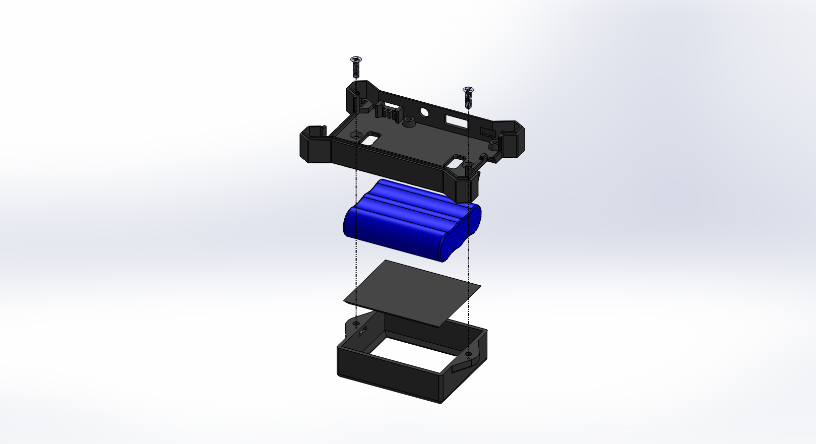
The rest of the build is more-or-less the same.
Play Your GameBoy
Hello old friend…

.
.
.
March 2020 UPDATE: Files are available here! Click the Download button below for a zip file.
Files are available under the Creative Commons BY-NC-SA license
14 Comments
Hi, it looks awesome, but one thing is preventing me of trying to build this one. The RetroPi has a lot more Emulators like an Gameboy Advance and N64, and for some of those Emulators you need more than those two round buttons. I would love it if you enhance this one (if possible) Then i’m going to built it with your setup. I like the Hexagon style 😉
Thanks, TjCo! Glad you like the style!
You shouldn’t have any issues with GBA emulation, as that was the primary system I was aiming this project for, and it’s got all the necessary buttons.
SNES and N64 would have more complications, as I’ve heard N64 emulation is really finicky for RetroPie and SNES can get laggy as well. However, if that’s what you’ve got your sights on, I’d recommend going with a Raspberry Pi 2 (it’s larger than the A+ though, and probably won’t fit into this case without significant modification, so keep that in mind). Haven’t gotten my hands on one of those yet, but hope to soon.
no sound?????
Thanks for the question, Pedro!
Sound is available through the headphone jack on the Raspberry Pi. There wasn’t enough room in the housing to include an audio amp and speaker, but some future Raspberry Pi projects I’m hoping to work on will.
Very nice work and beautiful design. Do you know if this project still works with raspberry pi 3 ? And also, how long your battery last ? Thank you.
Hi Gomazio! Thanks for the comment and questions.
This was designed to house the Raspberry Pi A+, so it likely won’t fit the Pi3 (or any other “B” style) without some modifications. However, there are plenty of other Gameboy designs out there that use the “B” style boards (adafruit.com being a huge resource).
The smaller battery will last a few hours, and the larger battery much, much longer. I apologize that I don’t have actual times recorded, but for reference, I’ve only needed to charge the larger battery once in the last six months.