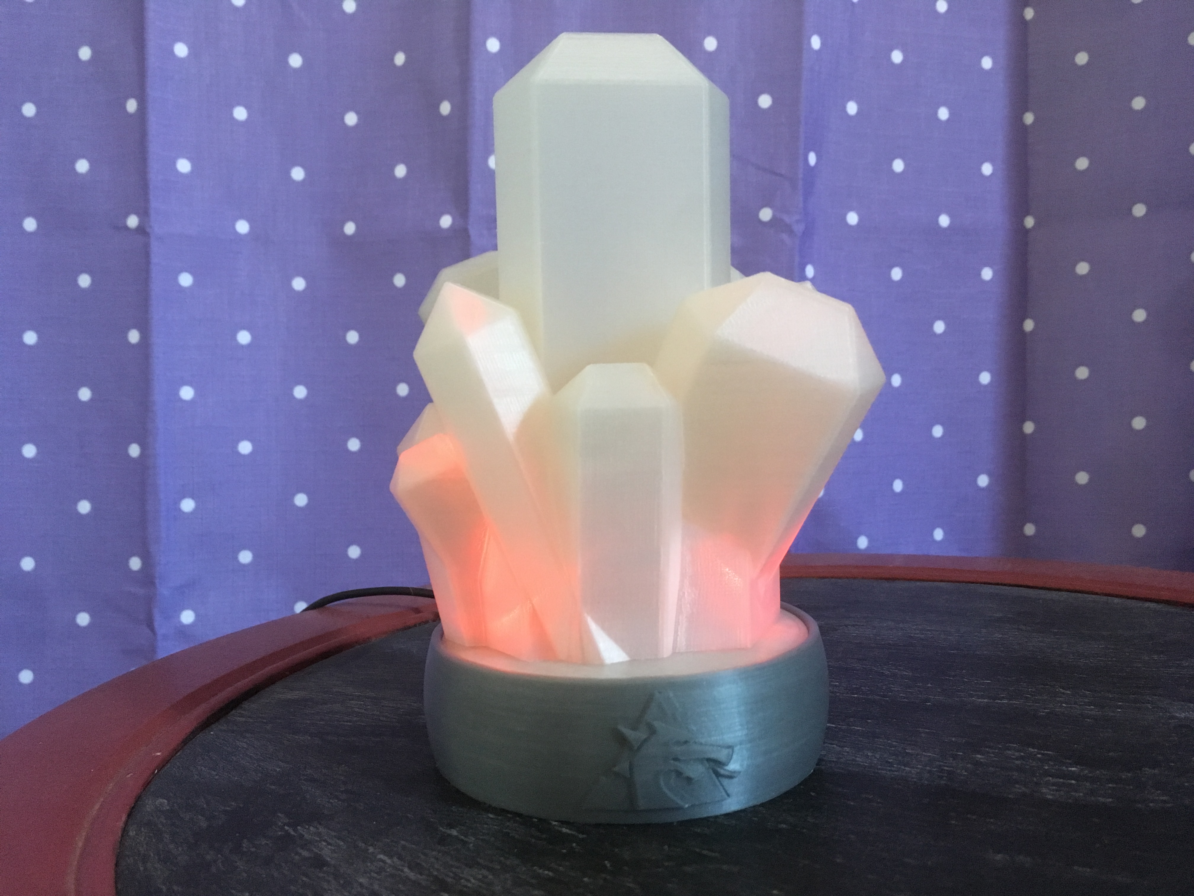
Crystal Nightlight
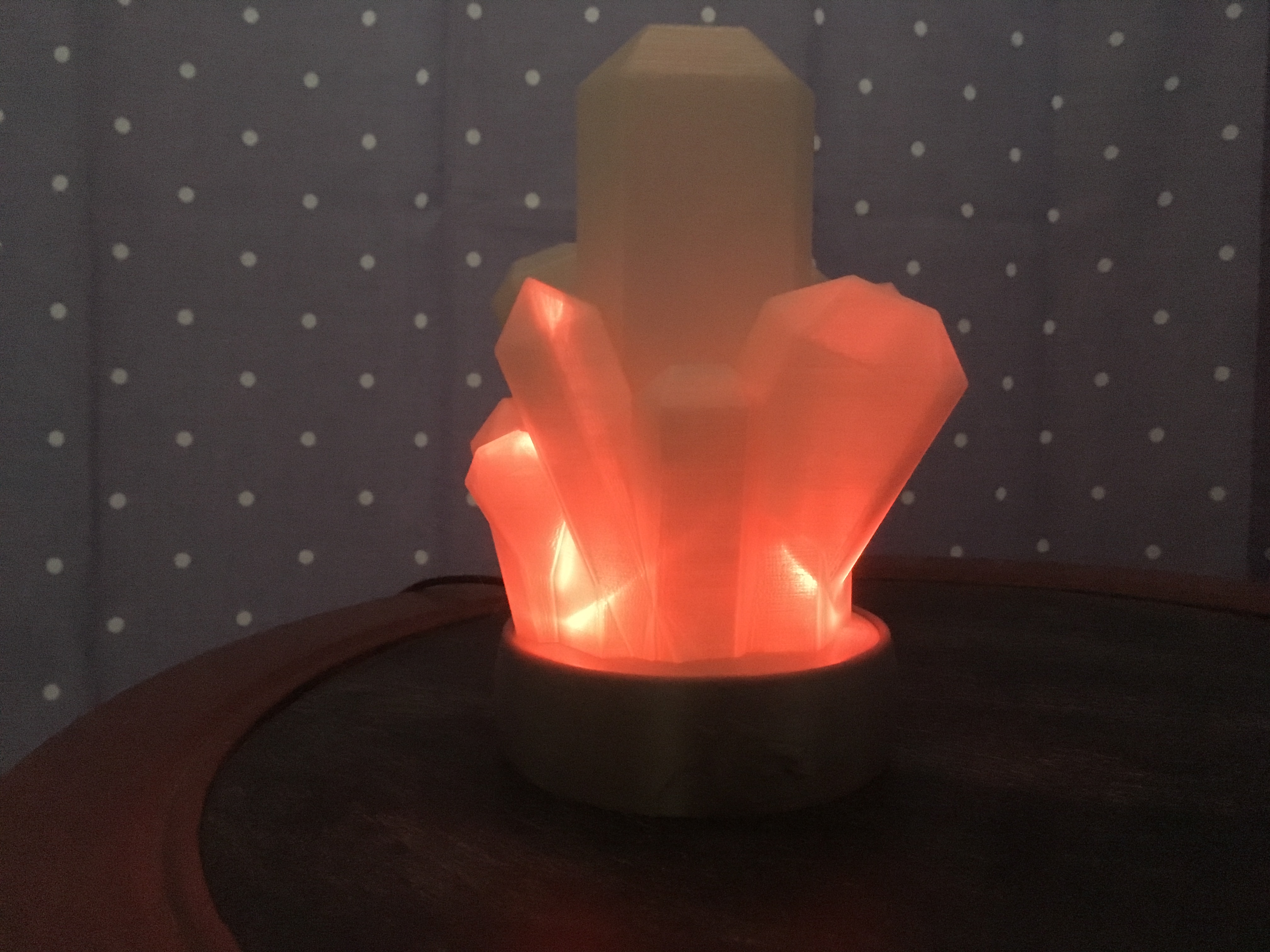
Finally! A project my 2-year-old understands and appreciates right out the gate. She’s thrilled. I’m thrilled.
At the beginning of the summer, my wife and I were discussing the design of our daughter’s “big-girl” room: paint, furniture, window treatments, etc. Around the same time, we were watching Trollhunters on Netflix, and I discovered a subreddit dedicated to mineral photos. The raw beauty of the natural structures our planet can generate under the correct circumstances came together with the whimsy and wonder of Troll Market, and the crystal nightlight was born.
Parts List:
Pro Trinket 5V 16MHz – Adafruit 2000
8/26/17 UPDATE: Super Bright Blue 5mm LED – Adafruit 301
Blue LEDs are not appropriate for nightlight, so they have been changed to Red. Thank you to Reddit user u/-Fateless- for the info on that.
Super Bright Red 5mm LED – Amazon (You can find them on Adafruit too, but were out of stock when I needed them).
Silicone Covered 26AWG Stranded-Core Wire, Red – Adafruit 1877
Silicone Covered 26AWG Stranded-Core Wire, Black – Adafruit 1881
Silicone Covered 26AWG Stranded-Core Wire, Blue – Adafruit 1878
Insulated Reed Switch – Sparkfun COM-10601
1/4″ OD x 1/8″ THK NdFeB, Grade N42 Magnet – K&J Magnetics D42
Heat-shrink tubing
USB micro cable and outlet adapter.
Helpful Tools:
3D Printer (or printing service)
E6000 Glue
Soldering Iron
Wire Strippers
Flush Cutters
Helping Hands
Vice
Print Parts
All files can be found on
Thingiverse,YouMagine, Cults3D, and MyMiniFactory.4/11/2018 UPDATE: Consolidating the number of places hosting the files. More changes to come, but they’re still available for free.
March 2020 UPDATE: Files can be downloaded directly from this site at the bottom of the page. They are also available on Prusa Printers!
Material: PLA
Color: Natural (for translucency) for all except CN-ElectronicHousing
Infill: 20%
Supports: CN-TriggerBottom only.
Brim: CN-TriggerBottom and CN-TriggerTop
Prep LEDs
Trim the negative lead and solder one 1 kΩ resistor to each one. Solder a length of wire (BLACK) to the end of the resistor. Cover area with heat shrink tubing.
Trim the positive lead and solder a length of wire (BLUE).

Do this for all five.
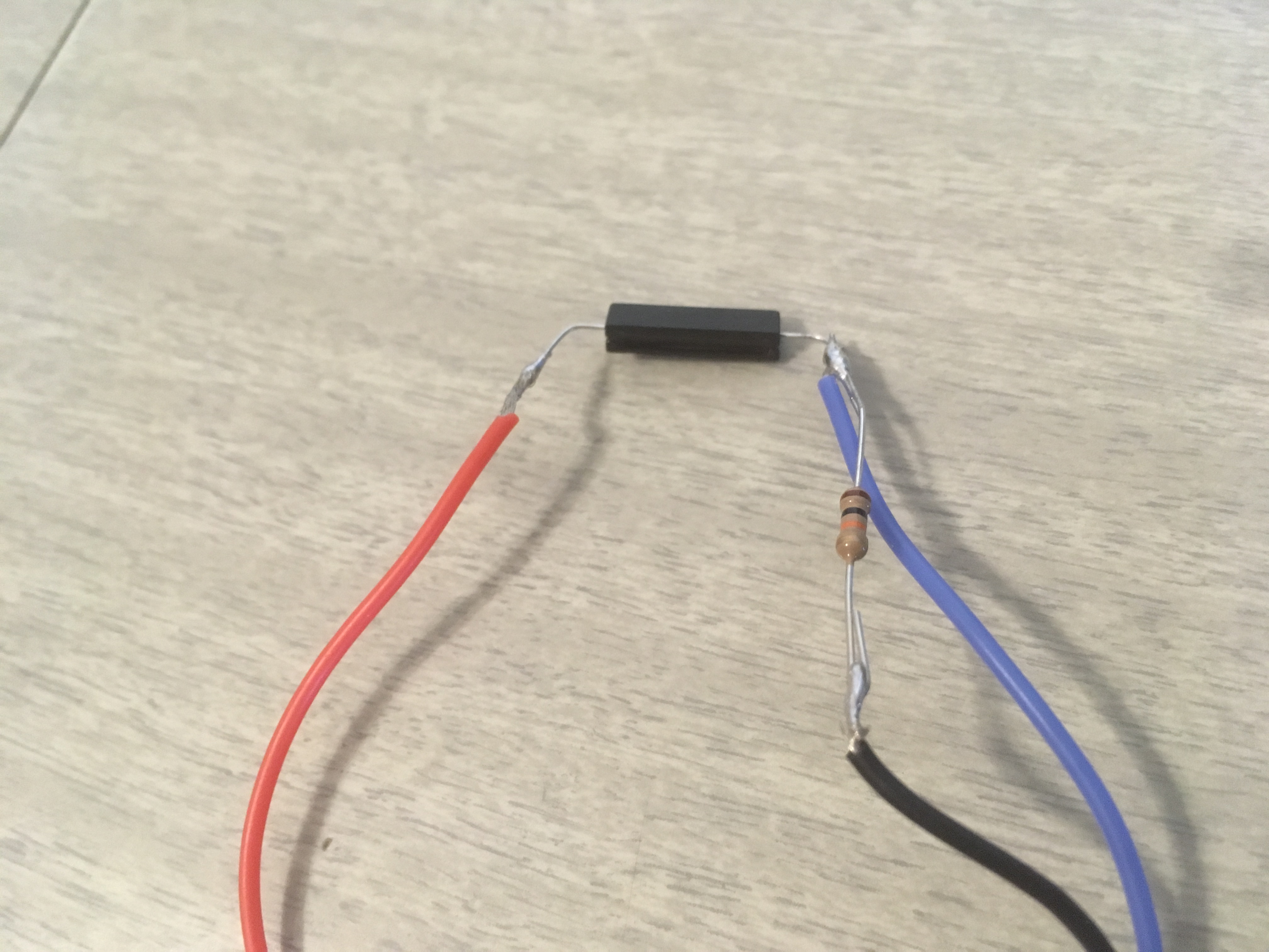
Prep Switch
Solder a length of wire (RED) to one end. Solder a 10 kΩ resistor and length of wire (BLUE) in parallel to the other end. Solder a length of wire (BLACK) to the end of the resistor.
Connect Components to Board
Solder a length of wire (BLACK) to GND, and connect the rest of the wires as shown.

Connect all black wires from the LEDs with the length going to GND, solder together, and cover with heat shrink.

Program Board
As my first step into programming in Arduino, the code is far from elegant, but it works, and I’m happy with that. It can be found either on TinkerCAD or GitHub.
For flashier results, feel free to write your own code. In the future, I’m intending to explore THIS resource recommended to me by the great Nate Philips.
If you’re unfamiliar on how to set everything up for the Pro Trinket, Adafruit has detailed information HERE.
Start up the board and test everything out before moving forward.
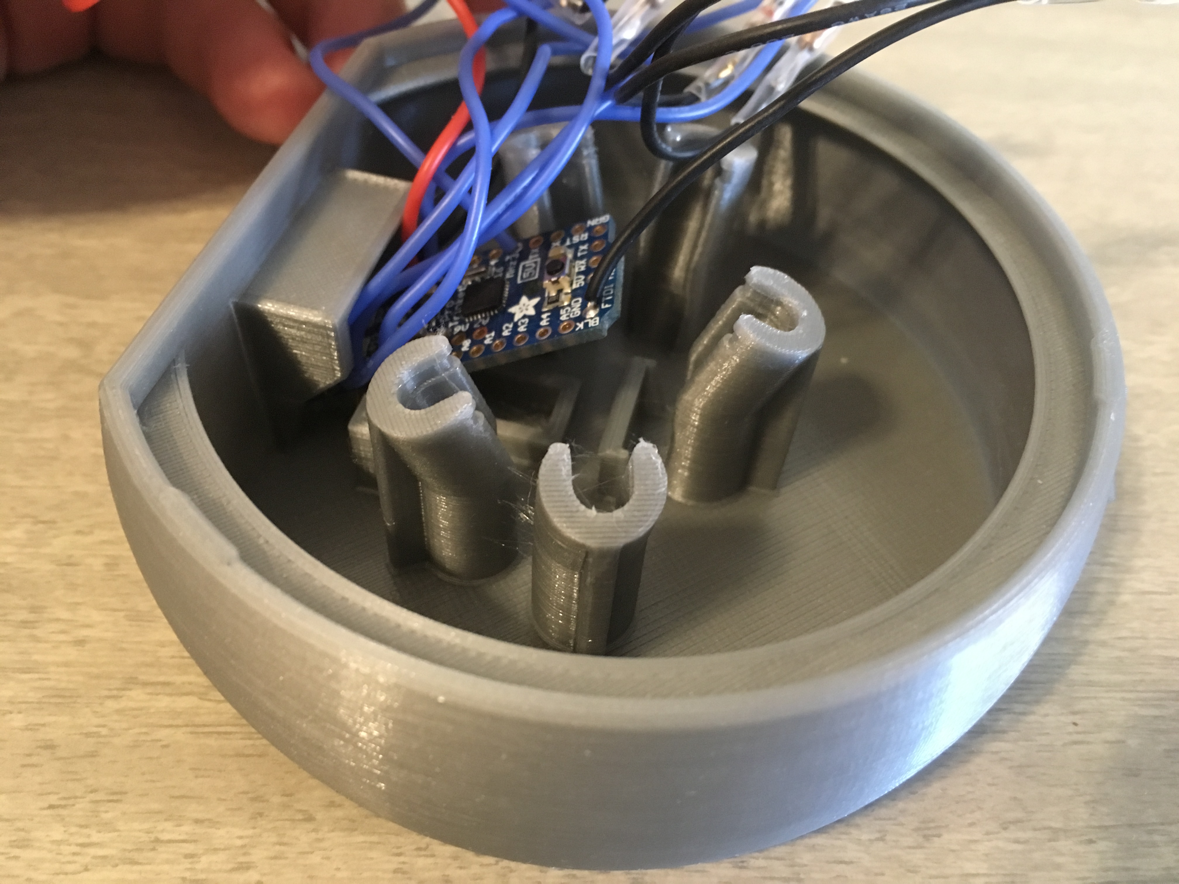
Install Electronics
Angle the Pro Trinket so that the end with the Micro USB connector fits into the connection area, and the mounting holes fit over the bumps. When in position, press the back end into place until it locks into position.

Press fit the LEDs into their holders as shown.
Fit the switch into CN-SwitchHolder, and press that assembly into CN-ElectronicsHousing.
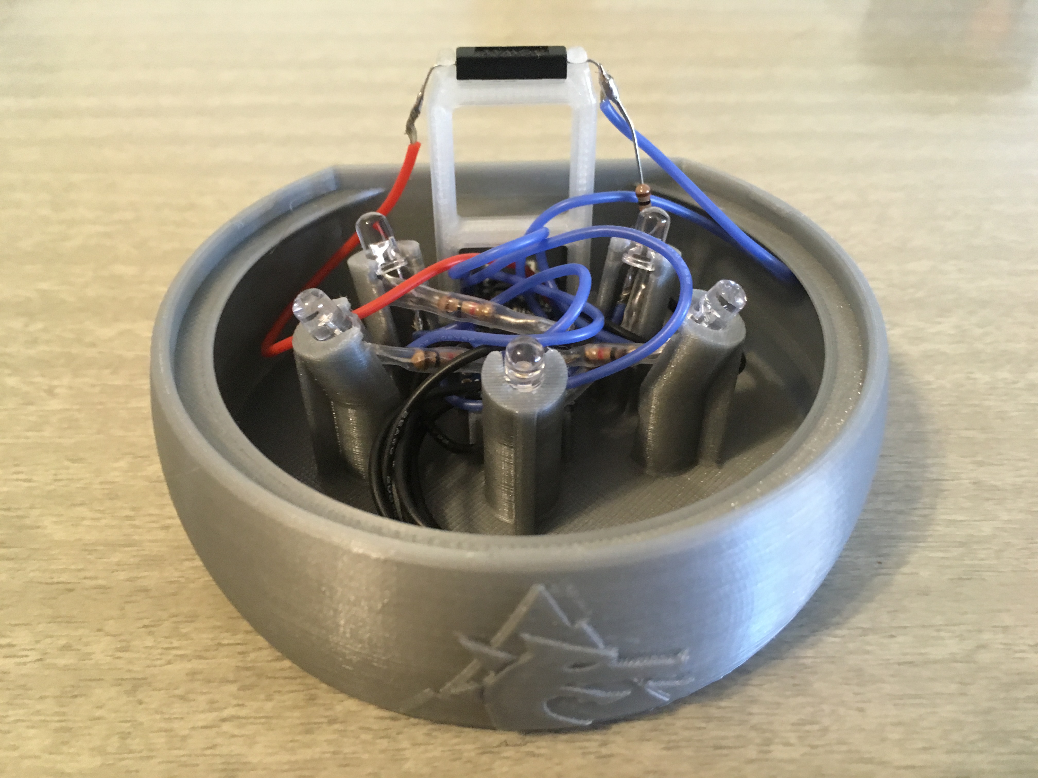
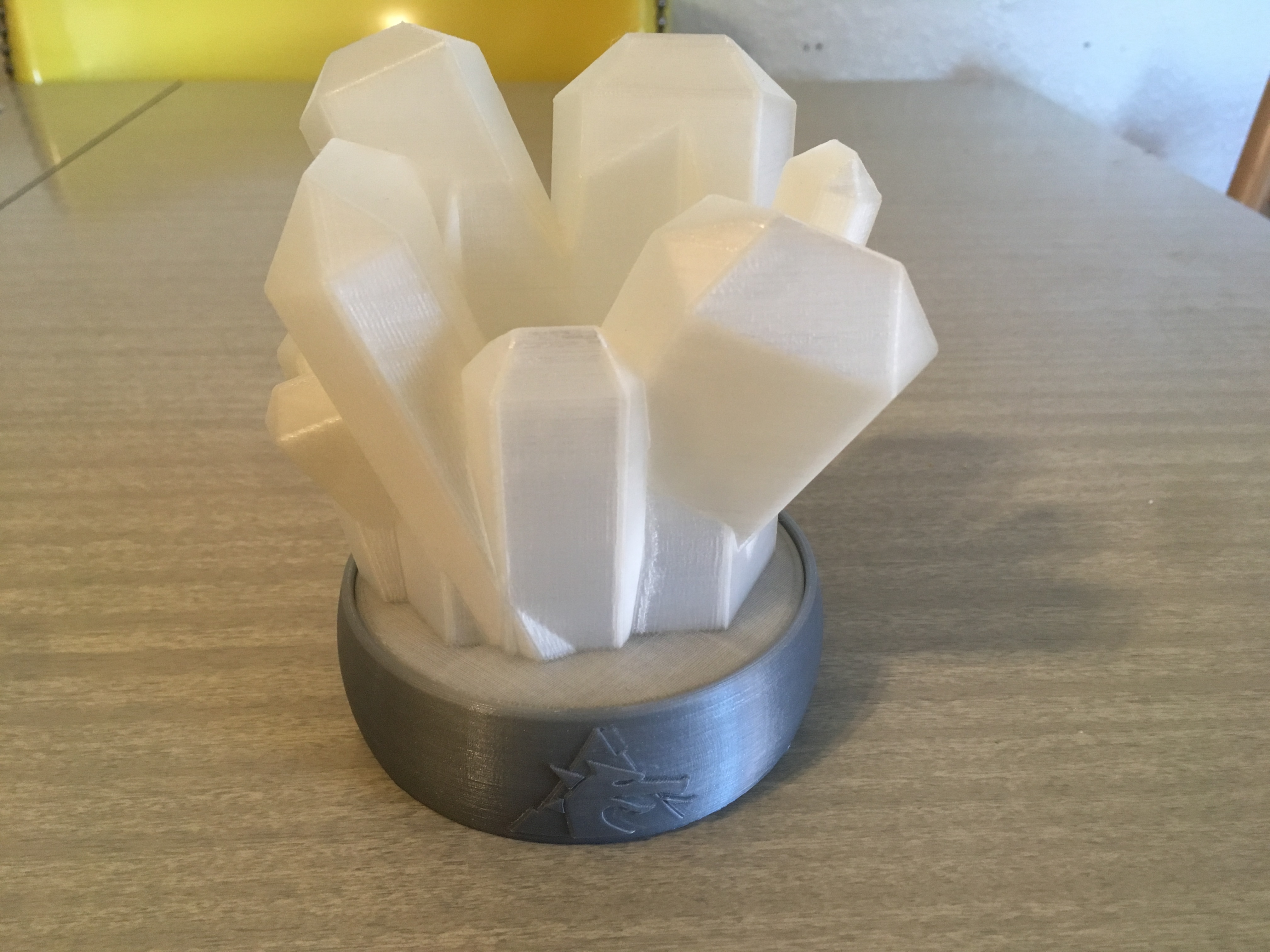
Assemble Cluster
Press fit CN-Cluster onto CN-ElectronicsHousing.
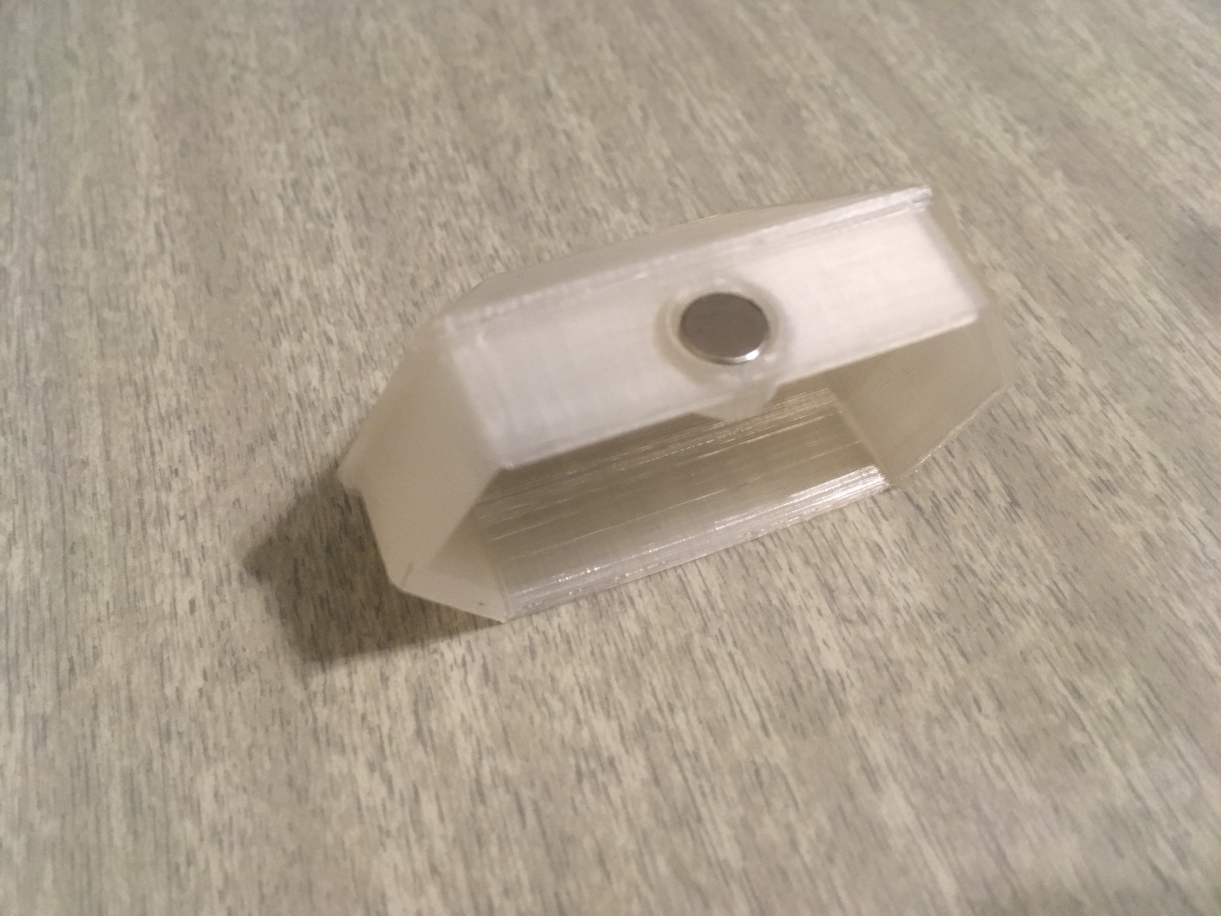
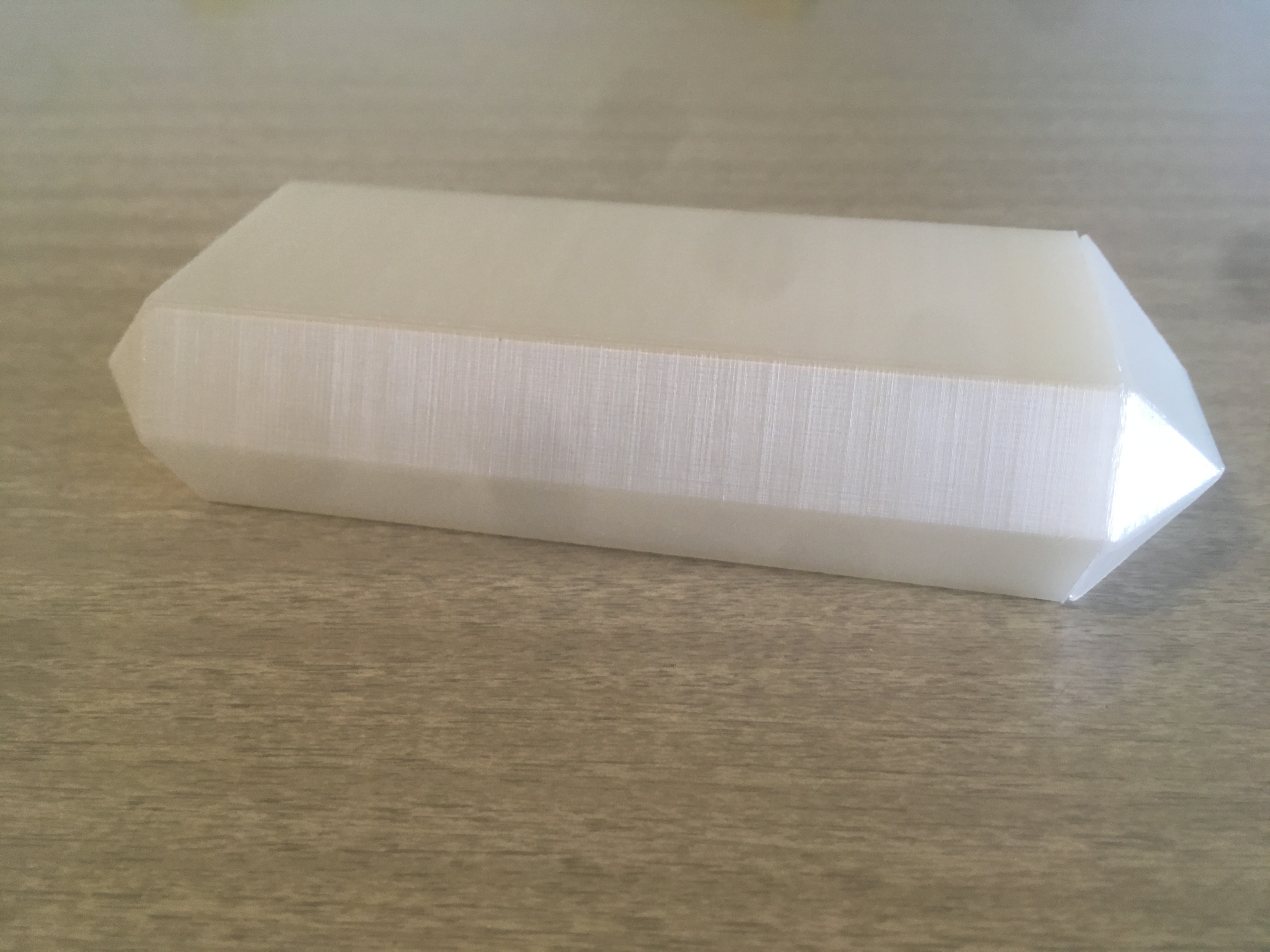
Assemble Trigger Crystal
Press the magnet into the recess of CN-TriggerBottom. Use a little E6000 glue and press CN-TriggerBottom into CN-TriggerTop.
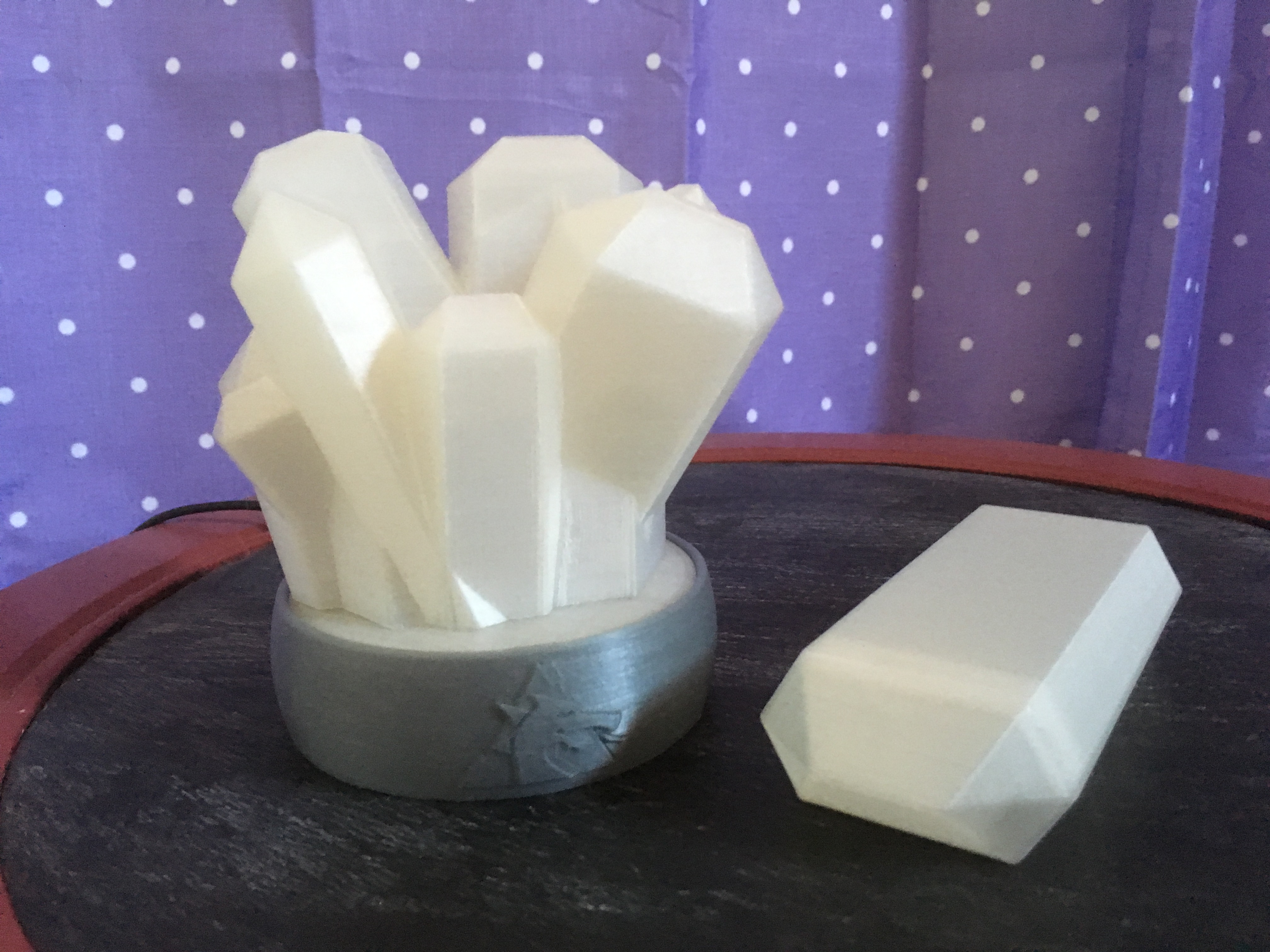
Light it Up
Plug the micro USB cable into a power source and connect it to the assembly.
Insert trigger crystal so that the part with the magnet is closest to the location of the reed switch.
Like what you see here? Follow me on Twitter @DragonMtnDesign for previews, updates, and to protect the world from Gunmar.
Full disclosure though, my wife and I are expecting our second child soon, so once DrachenDos decides to grace us with his or her presence, I’ll be taking little sabbatical from projects. I hope to crank out one more post before then though…
…Maybe a Cheekymandos Series 1 Finale (hint hint).
.
.
.
March 2020 UPDATE: Files are available here! Click the Download button below for a zip file.
Files are available under the Creative Commons BY-NC-SA license.
1 Comment
Cool concept, and awesome results! keep up the work and congrats.